We have compiled some calculation options for you. For liquids and gases it is possible to calculate the kv value, the flow Q and the pressure drop p. With the calculations for gases, one additionally distinguishes between the under-critical (p2 > p1/2) and over-critical cases (p2 < p1/2).
All calculations are purely practical formulas, i.e. simplifications for the respective case, which may only be used with the specified units.
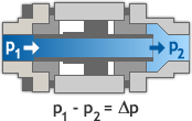
In order to calculate the flow Q the kvvalue, the density ρ1 of the media at the valve inlet and the pressure drop (Δp) across the valve must be known:
In order to measure the pressure drop Δp the kv value, the density ρ1 of the media at the valve inlet and the flow Q must be known:
In order to calculate the kv value the volumetric flow QN at 1013 hPa and 0°C, the standard density ρN of the media, the pressure drop (Δp) across the valve, the media pressure p2 downstream of the valve and the media temperature at the valve inlet must be known:
In order to calculate the flow QN the kv value, the standard density ρN of the media, the pressure drop (Δp) across the valve, the media pressure p2 downstream of the valve and the media temperature at the valve inlet must be known:
In order to calculate the pressure drop Δp the kv value, the volumetric flow QN at 1013 hPa and 0°C, the standard density ρN of the media, the media pressure p2 downstream of the valve and the media temperature at the valve inlet must be known:
| DN in mm |
Flow Velocity | |||||||||
| 0,5 m/s |
1,0 m/s |
1,5 m/s |
2,0 m/s |
3,0 m/s |
4,0 m/s |
5,0 m/s |
7,0 m/s |
8,0 m/s |
10,0 m/s |
|
| 8 | 1.5 | 3.0 | 4.5 | 6.0 | 9.0 | 12.1 | 15.1 | 21.1 | 24.1 | 30.2 |
| 10 | 2.4 | 4.7 | 7.1 | 9.4 | 14.1 | 18.8 | 23.6 | 33.0 | 37.7 | 47.1 |
| 12 | 3.4 | 6.8 | 10.2 | 13.6 | 20.4 | 27.1 | 33.9 | 47.5 | 54.3 | 67.9 |
| 15 | 5.3 | 10.6 | 15.9 | 21.2 | 31.8 | 42.4 | 53.0 | 74.2 | 84.8 | 106.0 |
| 16 | 6.0 | 12.1 | 18.1 | 24.1 | 36.2 | 48.3 | 60.3 | 84.4 | 96.5 | 120.6 |
| 20 | 9.4 | 18.8 | 28.3 | 37.7 | 56.5 | 75.4 | 94.2 | 131.9 | 150.8 | 188.5 |
| 25 | 14.7 | 29.5 | 44.2 | 58.9 | 88.4 | 117.8 | 147.3 | 206.2 | 235.6 | 294.5 |
| 32 | 24.1 | 48.3 | 72.4 | 96.5 | 144.8 | 193.0 | 241.3 | 337.8 | 386.0 | 482.5 |
| 40 | 37.7 | 75.4 | 113.1 | 150.8 | 226.2 | 301.6 | 377.0 | 527.8 | 603.2 | 754.0 |
| 50 | 58.9 | 117.8 | 176.7 | 235.6 | 353.4 | 471.2 | 589.0 | 824.7 | 942.5 | 1178.1 |
| 65 | 99.5 | 199.1 | 298.6 | 398.2 | 597.3 | 796.4 | 995.5 | 1393.7 | 1592.8 | 1991.0 |
| 80 | 150.8 | 301.6 | 452.4 | 603.2 | 904.8 | 1206.4 | 1508.0 | 2111.2 | 2412.7 | 3015.9 |
| 100 | 235.6 | 471.2 | 706.9 | 942.5 | 1413.7 | 1885.0 | 2356.2 | 3298.7 | 3769.9 | 4712.4 |
| 125 | 368.2 | 736.3 | 1104.5 | 1472.6 | 2208.9 | 2945.2 | 3681.6 | 5154.2 | 5890.5 | 7363.1 |
| 150 | 530.1 | 1060.3 | 1590.4 | 2120.6 | 3180.9 | 4241.2 | 5301.4 | 7422.0 | 8482.3 | 10602.9 |
| 200 | 942.5 | 1885.0 | 2827.4 | 3769.9 | 5654.9 | 7539.8 | 9424.8 | 13194.7 | 15079.6 | 18849.6 |
| 250 | 1472.6 | 2945.2 | 4417.9 | 5890.5 | 8835.7 | 11781.0 | 14726.2 | 20616.7 | 23561.9 | 29452.4 |
To avoid hydraulic shocks in pipelines, the flow velocities must be taken into account when designing valves for liquids.